 English
P10600HY070L_T01
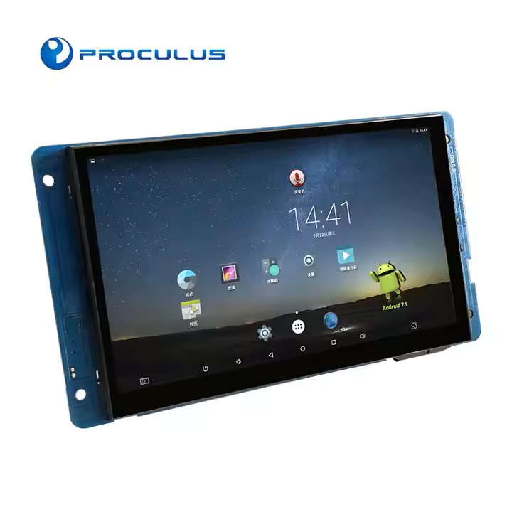
P10600HY070L_T01 is an industrial level Android LCM based on Rockchip RK3128 ARM. It is equipped with Quad-core Coretex-A7, supporting most decoding solutions under 1080p@60fps, H.265/H.264/MVC/VP8 solutions and many other great features of Rockchip RK3128. Meanwhile, with good jpeg picture processing performance and 3D GPU, it supports OpenGL ES2.0 and OpenVG1.1.
Rockchip RK3128 has high-performance external memory interface (DDR3/DDR3L/LPDDR2) capable of sustaining demanding memory bandwidths, also provides a complete set of peripheral interface to support very flexible applications.
Rockchip RK3128 has high-performance external memory interface (DDR3/DDR3L/LPDDR2) capable of sustaining demanding memory bandwidths, also provides a complete set of peripheral interface to support very flexible applications.
Specifications of 7 Inch Android LCD module
Core Board| CPU | 1.3 GHz Quad-core A7 ARM |
| RAM | 1GB DDR3 |
| eMMC | 8GB |
| GPU | Mali400MP2 |
| Power Management | AXP192 PMU |
| Android | Android 5.1/7.1 |
| Ubuntu | Ubuntu 15.04 (Default system is Android. Need to refresh firmware to choose Ubuntu. Apps need to be developed separately.) |
| Color | 16.7M (16777216) colors, 24-bit color 8R8G8B. |
| Active Area (A.A.) | 154.08 mm(W)×85.92 mm(H), 1024×600. |
| View Area (V.A.) | 155.96 mm(W)×88.87mm(H), 1024×600. |
| Resolution | 1024×600 |
| Backlight | LED |
| Brightness | 350/500/1000 |
| Item | Symbol | Condition | Min. | Typ. | Max. | Unit |
| Viewing Angle (CR≧10) | θL | Φ=180° (9 o’clock) | 70 | 80 | — | Degree |
| θR | Φ=0° (3 o’clock) | 70 | 80 | — | ||
| θT | Φ=90° (12 o’clock) | 50 | 60 | — | ||
| θB | Φ=270° (6 o’clock) | 60 | 70 | — |
| Item | Condition | Min. | Typ. | Max. | Unit |
| Power Voltage | 6 | 12 | 16 | V | |
| Operation Current | — | — | 400 | — | mA |
| Power Supply | 12V 2A DC (Recommended). | ||||
| Item | Condition | Min. | Typ. | Max. | Unit |
| Working Temperature | 60%RH at 12V voltage | -20 | 25 | 70 | ℃ |
| Storage Temperature | — | -30 | 25 | 85 | ℃ |
| Working Humidity | 25℃ | 10% | 60% | 90% | RH |
| Protection Paint | — | — | None | — | — |
| Serial Mode | Serial Port*3 (2*RS232/TTL, 1*RS485/RS232/TTL) |
| User Interface | Standard serial communication protocol. 8Pin_2.0mm socket. |
| USB | USB DEBUG*1. USB HOST*3 |
| Ethernet | Support 10m/100m Ethernet. |
| Wi-Fi/Bluetooth | Support 802.11b/g/n Wi-Fi wireless network; Bluetooth is optional. |
| 4G LTE Module | 4G LTE Module/GPS. (Optional) |
| Microphone | Audio input interface. |
| Loudspeaker | 2-channel, 4Ω/3W loudspeaker. |
| HDMI | — |
| IIC | Optional |
| TF card | Yes |
| GPIO | Reserved |
Interface Description of 7 Inch 1024*600 Android LCD Module
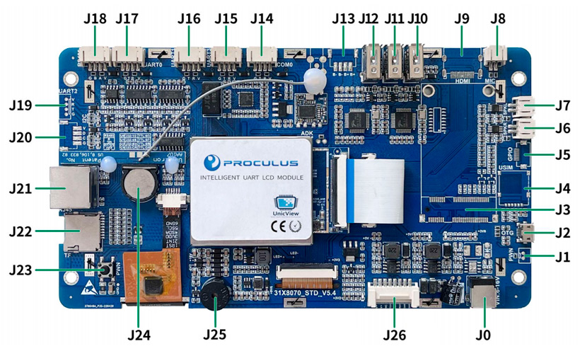
| Num. | Interface Name | Description |
| J0 | Power | 12V/2A power supply (maximum voltage ranges from 6V to 16V DC) |
| J1 | Wake-up | Control screen system on/off |
| J2 | USB_Micro | OTG /App debugging/ Firmware upgrade interface |
| J3 | MINI PCIE 4G | 4G LTE Module/GPS (Optional) |
| J4 | SIM card | Nano-SIM supported (Optional) |
| J5 | GPIO interface | Reserved, GPIO Number:13, 12, 11, 73, 74, 75 |
| J6 | SPK_R | Right channel audio output interface |
| J7 | SPK_L | Left channel audio output interface |
| J8 | MIC | Audio input interface |
| J9 | HDMI | – |
| J10 | USB_HOST3 | Support USB Peripherals |
| J11 | USB_HOST2 | Support USB Peripherals |
| J12 | USB_HOST1 | Support USB Peripherals |
| J13 | Debug interface | not open temporarily |
| J14 | COM0 | Device name: COM0. Pin definition: 5V, RXD, TXD, GND (Optional) |
| J15 | Debug interface | not open temporarily |
| J16 | UART1 | Device name: ttyS1. Pin definition: 5V, RXD, TXD, GND |
| J17 | UART0 | Device name: ttyS0. Pin definition: 5V, RXD, TXD, GND/Same as J18 |
| J18 | RS485 | Device name: ttyS0. Pin definition: 5V, A, B, GND/Same as J17 |
| J19 | Debug interface | not open temporarily |
| J20 | IIC communication | Pin definition: 5V, SDA, SCL, GND (Reserved) |
| J21 | RJ45 interface | Support 10M/100M network |
| J22 | TF card | Can do memory expansion |
| J23 | Wake-up | Control screen system on/off |
| J24 | RTC | Supply system RTC |
| J25 | Buzzer | Buzzer |
| J26 | User interface | Pin Definition: 12V, 12V, NC, TXD, RXD, RXD, GND, GND |
Products
-
UART TFT LCD Module
-
7.0 Inch 1024*600 LCD Module


-
10.1 Inch 1024*600 LCD Module
-
9.7 Inch 1024*768 LCD Module
-
8.0 Inch 800*600 LCD Module
-
7.0 Inch 800*480 LCD Module
-
4.3 Inch 800*480 LCD Module
-
5.0 Inch 800*480 LCD Module
-
3.5 Inch 640*480 LCD Module
-
4.3 Inch 480*272 LCD Module
-
2.8 Inch 240*320 LCD Module
-
15.0 Inch 1024*768 LCD Module
-
2.8 Inch 320*240 LCD Module
-
2.8 Inch 320*240 LCD Module
-
3.5 Inch 320*240 LCD Module
-
3.5 Inch 320*240 LCD Module
-
4.3 Inch 480*272 LCD Module
-
4.3 Inch 480*272 LCD Module
-
4.3 Inch 480*272 LCD Module
-
5.0 Inch 800*480 LCD Module
-
7.0 Inch 800*480 LCD Module
-
7.0 Inch 800*480 LCD Module
-
7.0 Inch 800*480 LCD Module
-
7.0 Inch 1024*600 LCD Module
-
7.0 Inch 800*480 LCD Module
-
7.0 Inch 800*480 LCD Module
-
7.0 Inch 1024*600 LCD Module
-
8.0 Inch 800*600 LCD Module
-
8.0 Inch 800*600 LCD Module
-
8.0 Inch 800*600 LCD Module
-
10.1 Inch 1024*600 LCD Module
-
10.1 Inch 1024*600 LCD Module
-
10.4 Inch 800*600 LCD Module
-
10.4 Inch 800*600 LCD Module
-
10.4 Inch 800*600 LCD Module
-
15.0 Inch 1024*768 LCD Module
-
15.0 Inch 1024*768 LCD Module
-
Starter Kit
-
7.0 Inch 1024*600 LCD Module
-
Android LCD Module
-
7.0 Inch 1024*600 Android LCD Module
-
15.6 Inch 1920*1080 Android LCD Module
-
10.1 Inch 1280*800 Android LCD Module
-
7.0 Inch 1024*600 Android LCD Module
-
7.0 Inch 1024*600 Android LCD Module
-
10.1 Inch 1280*800 Android LCD Module
-
Box Android LCD Module
-
7.0 Inch 800*480 Android LCD Module
-
5.0 Inch 480*272 Android LCD Module
-
15.0 Inch 1024*768 Android LCD Module
-
8.0 Inch 1024*768 Android LCD Module
-
7.0 Inch 1024*600 Android LCD Module
-
5.0 Inch 800*480 LINUX LCD Module
-
4.0 Inch 480*480 Android LCD Module
-
5.0 Inch 800*480 Android LCD Module
-
5.0 Inch 800*480 Android LCD Module
-
7.0 Inch 1024*600 Android LCD Module
-
7.0 Inch 1024*600 Android LCD Module
-
7.0 Inch 1024*600 Android LCD Module
-
7.0 Inch 1024*600 Android LCD Module
-
7.0 Inch 1024*600 Android LCD Module
-
7.0 Inch 1024*600 Android LCD Module
-
7.0 Inch 1024*600 Android LCD Module
-
7.0 Inch 1024*600 Android LCD Module
-
8.0 Inch 1024*768 Android LCD Module
-
10.1 Inch 1280*800 Android LCD Module
-
10.1 Inch 1280*800 Android LCD Module
-
10.1 Inch 1280*800 Android LCD Module
-
10.1 Inch 1280*800 Android LCD Module
-
15.0 Inch 1024*768 Android LCD Module
-
15.0 Inch 1024*768 Android LCD Module
-
18.5 Inch 1366*768 Android LCD Module
-
18.5 Inch 1366*768 Android LCD Module
-
7.0 Inch 1024*600 Android LCD Module
-
Display HDMI
PHP Code Snippets Powered By : XYZScripts.com